0
Differential pressure inputs
Dual sensor channels with ±500 Pa range per channel.
Compact dual differential-pressure monitoring with live touchscreen readings, configurable alarms, alarm history, and Modbus communication for industrial integration.

Product overview
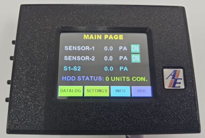
ASAS monitors two differential pressure sensors, displays Sensor-1, Sensor-2, and the calculated S1-S2 value in Pa, and gives operators direct access to datalog, settings, and device information from the home screen.
The controller combines a 2.8 inch resistive touchscreen, local buzzer, relay output, alarm history, IP configuration, and Modbus RTU serial configuration in one compact 114 x 84 x 37 mm package.
Dual sensor channels with ±500 Pa range per channel.
Sensor 1, Sensor 2, and active alarm flag for supervisory systems.
Recent alarm events with date and time for review and investigation.
Serial Modbus RTU communication for external system integration.
Key features
Designed for straightforward commissioning, clear local operation, and reliable integration with site systems.
Live values for Sensor-1, Sensor-2, and S1-S2 differential pressure in Pa.
2.8 inch TFT RGB 65K resistive touchscreen with clear menu navigation.
Built-in alarm buzzer with NO/NC relay output rated 250VAC 1A.
Modbus TCP and Modbus RTU communication for connected systems.
Set sensor names, low and high limits, offsets, alarm delays, and sensor enable/disable state.
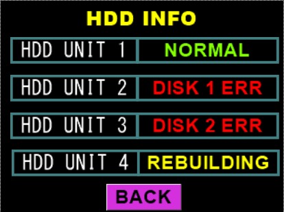
Review alarm log records with sequence, date, time, sensor, state, and Pa value.
Technical snapshot
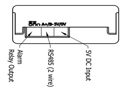
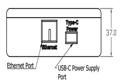
ASAS is powered through USB-C or 5VDC input and provides Ethernet, Modbus RTU, pressure sensor input, and alarm relay connections in a compact enclosure.

| Power | USB-C or 5VDC input |
|---|---|
| Display | 2.8 inch TFT RGB 65K, 320 x 240, resistive touch |
| Sensors | Differential pressure sensors, ±500 Pa x 2 |
| Alarm output | Buzzer and relay output, NO/NC, 250VAC 1A |
| Comms | Modbus TCP / Modbus RTU communication |
| Registers | HR1 DP Sensor 1 Value, HR2 DP Sensor 2 Value, HR3 active alarm flag |
| Configurable | Sensor name, low limit, high limit, offset, alarm delay, enable/disable |
| Alarm log | 10 alarm history entries with date and time |
| Dimensions | 114 x 84 x 37 mm (W x H x D) |
On-device interface
Operators can move from the main page to datalog, settings, or info screens. Settings pages provide access to naming, high and low limits, offsets, bypass, alarm delay, clock, IP, and Modbus RTU configuration.
View Sensor-1, Sensor-2, and S1-S2 in Pa from the home screen.
Check sequence, date, time, sensor, state, and alarm value.
Edit sensor names, limits, offsets, bypass state, and alarm delay.
Configure IP address and Modbus RTU values, then restart to apply changes.
Views and interface
Click any image to enlarge.
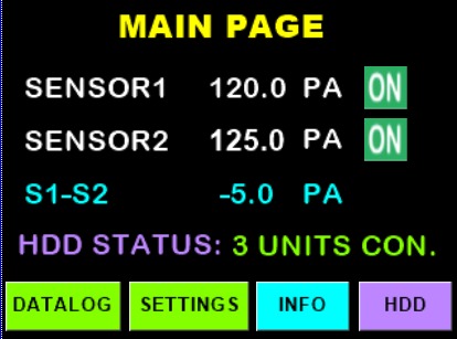
Main touchscreen
The main page shows the current time and date, live sensor values, calculated S1-S2 differential value, and quick access to Datalog, Settings, and Info.
Operation notes
Use ASAS together with site SOPs and commissioning records before changing settings.
Talk to Anson Engineering about differential pressure monitoring, alarm integration, commissioning requirements, and site-specific configuration.